Collins 30L1 HF amplifier ham amateur radio 811A linear round emblem bad relay
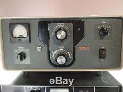
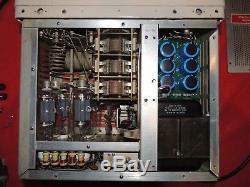
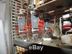
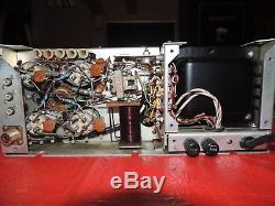

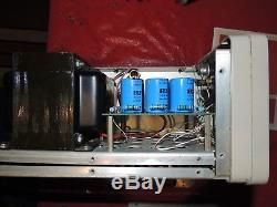
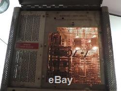

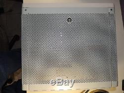
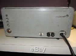

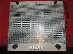


This is a used round emblem Collins 30L-1 ham radio HF amplifier with (4) brand new Svetlana tubes (white ceramic bases) with new Harbach power supply (1n5408 rectifiers and 220uf 450vdc electrolytics). When I bought the amplifier there was evidence of a flashover and I replaced the 47 ohm grid resistors and tubes at the same time i replaced the power supply. The relay will not engage and I have isolated it to the relay coil and the 2k 7w in parallel with it, they both seem to be "open". The power supply shows 2000 vdc with no load after the Harbach installed. Resting current is approx 120ma or so with bias resistor 39 ohms (per rev 9 manual, not 47 ohms per older revisions). The cabinet has been repainted and looks good. The power cord has been replaced. The trim ring has been repaired and painted.
The front panel looks pretty good as you can see in the pictures. The meter works and you can see the plate unloaded voltage in one of the pictures and the resting current in another. THE COLLINS 30L-1 LINEAR AMPLIFIER-2, the 30L-1 has all the controls conveniently accessible on the front panel.
The Collins 30L-1 Linear Amplifier has 1000 watts PEP power input on SSB and 1000 watts average on CW on all bands. It can be driven by the Collins 32S-3 Transmitter Collins KWM-2 or KWM-1 Transceiver, or most 70-100 watt exciters. Finished in the same attractive light gray as Collins' famous S/Line equipment and the KWMThis linear amplifier is completely self-contained and designed for table-top use. It is easily transported in a CC-2 Carrying Case. AUTOMATIC LOAD CONTROL allowing a high average level of modulation and optimum power output from the amplifier, within the rated limits of distortion. RF INVERSE FEEDBACK reduces distortion products giving cleanest signal on the air. SOLID STATE RECTIFIERS resulting in heat reduction. SELF-CONTAINED POWER SUPPLY with safety interlock circuits for grounding the high voltage when the cover is removed. AUTOMATIC ANTENNA TRANSFER ON THE ON-OFF SWITCH permits the 30L-I to be switched in or out of the circuit at will by operating the switch. The 30-L-1 provides SSB and CW emission and covers the 80, 40, 20, 15 and 10 meter bands. Provisions are made for general coverage use, too. Automatic Load Control voltage from the 30L-1 is fed back to the exciter, providing maximum talking power without over driving and distortion. In combination with RF inverse feedback, Collins' exclusive Automatic Load Control provides not only more power, but a sharper signal than any comparable unit in the amateur field. The 30L-1 is a grounded grid linear amplifier with four 811 A Triodes. They can be replaced without removing the unit from the cabinet. The 811A's are instantly heated; thus, there is no delay in warm-up. Indicating devices on the 30L-1 include a panel meter monitoring final amplifier plate current, plate voltage, and tuning circuit. With the meter switch in tune position, the 30L-1 uses an exclusive comparator circuit which can be operated by simply adjusting tuning and loading controls to zero the meter. The 30L-1's RF and power supply compartment covers operate safety interlock switches for protection of the operator.The unit can be operated outside amateur band limits; however, retuning the input circuits may be necessary. Such retuning presents the proper load impedance to the exciter. FREQUENCY RANGE: 3.4 - 30.0 mc, covering 80, 40, 20, 15 and 10 meter amateur bands. BY retuning input circuit as necessary, the following general coverage bands can he accommodated: FREQUENCY BAND TOTAL COVERAGE 3.5 mc 3.4- 5.0 mc 7.0 mc 6.5- 9.5 mc 14.0 mc 9.5-16.0 mc 21.0 mc 16.0-22.0 mc 28.0 mc 22.0-30.0 mc MODE: SSB or CW. TYPE OF SERVICE: Attended operation SSB continuous; CW 50% duty cycle.
POWER REQUIREMENTS: 115 v or 230 v, 50-60 cps; CW, key closed, 1200 watts ac; SSB, no modulation, 300 watts ac; SSB, speech modulated, 550 watts ac. DRIVE POWER: 70 - 100 watts for full output. PLATE POWER INPUT: 1000 watts PEP on SSB; 1000 watts on CW on all bands. POWER OUTPUT: 500 watts PEP into 50 ohms on all bands. HARMONIC AND OTHER SPURIOUS RADIATION: Second harmonic -40 db; third order distortion -30 db at full output. NOISE LEVEL: 40 db below one tone carrier. AMBIENT TEMPERATURE: 0 - 50 C.Nominally 50 ohms unbalanced with not more than 2:1 SWR on the amateur hands. AUDIO COMPRESSION CHARACTERISTICS: ALC operates from the amplifier RF plate voltage. Threshold is adjustable and factory preset. The 30L-1 is a portable r-f linear power amplifier, including plate power and bias supplies. It is capable of 1000 watts PEP input power in SSB or 1000 watts d-c input in CW service with any exciter (such as the KWM-1, KWM-2/2A, or 32S-1) capable of 70 watts PEP output.
It covers the amateur bands between 3.5 and 29.7 mc. In addition, the amplifier may be operated outside the amateur bands over certain ranges of frequency. These ranges are specified in above. The power amplifier stage uses four 811A triodes connected in parallel with cathode drive.Broadband pi-network circuits couple the exciting signal into the cathode circuits of the power amplifier tubes. In conjunction with the interconnecting r-f feed cable supplied, this presents a nearly constant 50-ohm load to the exciter This aids in maintaining the low level of distortion products under modulation.
For this reason, it is important not to alter the length of interconnecting cable supplied with the amplifier. The plate circuit of the power amplifier is tuned by a pi network consisting of C32, L9, L10, and C33.
Capacitor C32 resonates the tank circuit at the frequency in use. It is adjusted by the TUNING control on the front panel. The four-gang capacitor, C33, is adjusted by the LOADING control to match the pi-network circuit to the impedance presented by the antenna and feed system in use.
Output from the plate tank circuit is connected through the contacts of antenna changeover relay, K1, to the antenna when the control circuits are energized. Two dc power supplies and one a-c filament supply are included in the 30L-1. The amplifier may be connected to a 115-volt single-phase or to a 230-volt, three-wire, single- phase source. Where practical, the 230-volt, three-wire connection is recommended.Power transformer T1 has two primary windings. These windings are connected in parallel for 115-volt operation, and in series for 230-volt operation. The 6.3-volt secondary winding provides filament power for the 811A tubes through r-f choke L8.
It also powers the pilot lamp in the meter. Another secondary winding applies voltage through surge resistor R9 to semiconductor rectifier CR20. This is a half-wave circuit connected to furnish blocking bias to the amplifier tubes under receive conditions and operating bias when transmitting. It also furnishes power for changeover relay K1. Voltage from the third secondary winding is applied to two semiconductor rectifier strings connected in full-wave voltage doubler configuration. These strings consist of CR1-CR8, C44-C51 in one string, and CR9-CR16, C52-C59 in the other. The parallel capacitors equalize the reverse voltages impressed across the diode junctions and protect against damage by transients. The output of this supply provides approximately 1600 volts dc under load for the amplifier tube plates. The rf and power supply compartment covers operate safety interlock switches for operator protection. Switch S5 is located in the power supply compartment.Switches S6 and S7 are located in the rf compartment. This arrangement protects the operator from accidentally coming in contact with high-voltage d-c which is present in either compartment.
The front-panel ON-OFF switch breaks one side of the a-c line in the OFF position. When operated to the ON position, a-c power is applied to the power transformer primaries and the tube-cooling fan B1. Overload protection is provided by eight-ampere fuses F1 and F2. These are used for both 115-volt a-c and 230-volt a-c operation.It is coupled to the alc rectifier CR19 through capacitor C72. The r-f voltage is rectified and filtered to produce a negative d-c control voltage which is proportional to the modulation level. The load resistor for CR19 must be provided by the exciter alc circuits. This voltage is applied to the control grid of a low-level r-f amplifier tube or tubes in the exciter. The time constants of these circuits have fast attack, slow- release characteristic.
The alc threshold is controlled by the amount of reverse bias on CR19. This voltage is developed across R7 in the plate supply bleeder network, and varied by potentiometer R16.
It is adjusted at the factory for optimum operation in conjunction with the internal alc circuits of exciters such as the KWM-1, KWM-2/2A, or 32S-1. Normally it will not need readjustment. This system allows a high average level of modulation and optimum power output from the amplifier, within the rated limits of distortion. One section of the METER switch, S3, selects the output voltage from a tuning and loading bridge circuit. This circuit consists of the power amplifier tubes, CR17, CR18, and the associated load resistors and filter networks. The bridge is balanced when the plate circuit TUNING and LOADING controls are adjusted to present the proper load impedance to the power amplifier plates. The meter then will read zero. The second section of the meter switch connects the meter to the plate supply through a four-megohm multiplier resistor to indicate the dc voltage output. It is read on the D. The third section of the meter switch connects the meter, through R10, across shunt, R8. This indicates power amplifier plate current. The item "Collins 30L1 HF amplifier ham amateur radio 811A linear round emblem bad relay" is in sale since Sunday, December 16, 2018. This item is in the category "Consumer Electronics\Radio Communication\Ham, Amateur Radio\Ham Radio Amplifiers".- Brand: Collins
- Model: 30L-1
- Max. Output Power: 600 W
- Band: HF
- Supported Modes: CW
- Country/Region of Manufacture: United States


